Showing posts with label Automation / PLC. Show all posts

ALLEN BRADLEY PLC


MODEL NO: MICROLOGIX 1200 SERIES C
INPUT: 14 & OUTPUT: 10
COMMUNICATION PROTOCOL: RS 232


TO OPEN THE SOFTWARE


Then select CPU model 

 FILE – NEW – SELECT  (MICROLOGIX 1200 SERIESC)

Hardware configuration:


DIGITAL INPUT / DIGITAL OUTPUT (14/10):

INPUT:        I: 0/0    to   I: 0/13

OUTPUT:   O: 0/0   to   O: 0/9

INTEGER:      N7:0                             N7:255

FLOAT:       F8:0    F8:255

BINARY:    B3:0/0    to    B3:0/15
          
                B3:255/0    to  B3:255/15

CONTROL REGISTER: R6:0   to   R6:255

JUMP:          Q2:0  to Q2:99

SUB ROUTINE: U:3    to  U:99

STRING:      ST9:0  to  ST9:255

ANALOG (2/2)

INPUT:         I:1.0 AND I:1.1
OUTPUT:     O:1.0 AND O:1.1

USER:
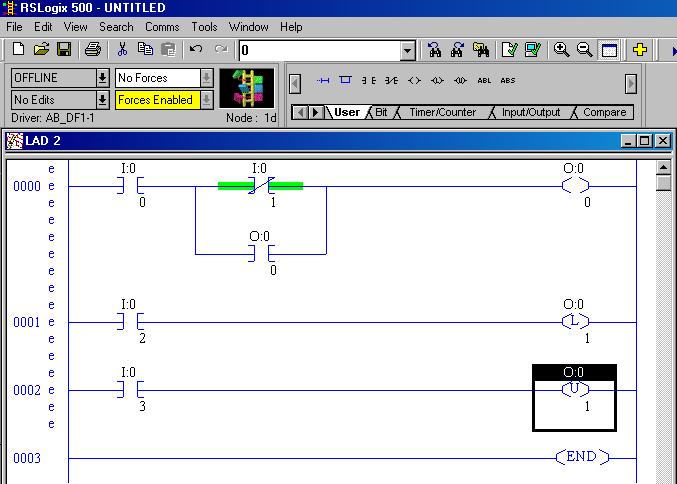
  • NO CONTACT
  • NC CONTACT
  • LOAD
  • LATCH COIL
  • UN LATCH COIL


BIT:
1.ONE SHOT
2.ONE SHOT RISING
3.ONE SHOT FALLING


1.ONE SHOT:
It produces it pulse during off state to on state. It does not have output bit

2. ONE SHOT RISING:
It produces its pulse during of state to on state.


3. ONE SHOT FALLING:
It produces its output pulse during on state to off state


Timer and Counter Instructions

If You Want to:                        Use This Instruction:
Delay turning on an output                         TON
Delay turning off an output                         TOF
Time an event retentively                            RTO
Count up                                                   CTU
Count down                                              CTD
Reset the accumulated value
and status bits of a timer or
counter.(Not used with
 TOF timers.)                                             RES       

    
COMPARE INSTRUCTION:

If You Want to ...

Test whether two values are equal (=) EQU
Test whether one value is not equal to a second value (><) NEQ
Test whether one value is less than a second value (<) LES
Test whether one value is less than or equal to a second value (<=) LEQ
Test whether one value is greater than a second value (>) GRT
Test whether one value is greater than or equal to a second value (=>) GEQ
Test portions of two values to see whether they are equal MEQ
Test whether one value is within the limit range of two other values LIM
 COMPUTE / MATH:

If You Want to                                                               Use This Instruction

Add two values                                                                         ADD
Subtract two values                                                                   SUB
Multiply one value by another                                                    MUL
Divide one value by another                                                       DIV
Change the sign of the source
 value and place it in thedestination                                             NEG

If You Want to                                                             Use This Instruction

Set all bits of a word to zero                                                       CLR
Convert an integer value to BCD                                                  TOD
Convert a BCD value to an integer
 value                                                                                        FRD  


SQUARE ROOT (SQR):
Find the square root of a value

GRAY CODED DECIMAL(GCD):
This output instruction converts the Gray code Source to integer and places it in the  Destination. On a True rung, this instruction sets the value of the Destination to the integer value corresponding to the Gray code Source. If the Gray code input is negative (high bit set), the destination is set to 32767 and the overflow flag is set. The GCD instruction only operates on Word operands.
 MOVE / LOGICAL INSTRUCTION:

If You Want to                                                                   Use This Instruction

Move the source value to the destination                                           MOV
Move data from a source location to a
selected portion of the destination                                                     MVM
Perform an AND operation                                                              AND
Perform an inclusive OR operation                                                   OR
Perform an Exclusive Or operation                                                   XOR
Perform a NOT operation                                                                NOT         

MOVE:
When rung conditions preceding this instruction are true, the MOV instruction moves a copy of the source to the destination each scan. The original value remains intact and unchanged in its source location.


MASKED MOVE:
When rung conditions are true, the MVM instruction moves data from a source location to a destination, and allows portions of the destination data to be masked by a separate word. Data at the source address passes through the mask to the destination address. As long as the rung remains true, the instruction moves the same data each scan.


CLEAR:
When rung conditions are true, this output instruction sets all the bits in a word to zero. The destination must be a word address.


AND: 
When rung conditions are true, sources A and B of this output instruction are ANDed bit by bit and stored in the destination.
PROGRAM CONTROL:

If You Want to                                                                          Use This Instruction

Jump forward/backward to a
corresponding label instruction                                                          JMP, LBL
Jump to a designated subroutine and return                                     JSR, SBR, RET
Enable or inhibit a master control zone
 in your ladder program                                                                       MCR
Truncate program scan                                                                          TND

JUMP:
When the rung condition for this output instruction is true, the processor jumps forward or backward to the corresponding label instruction (LBL) and resumes program execution at the label. More than one JMP instruction can jump to the same label. Jumping forward to a label saves program scan time by omitting a program segment until needed. Jumping backward lets the controller execute program segments repeatedly.


JUMP TO SUBROUTINE:
When rung conditions are true for this output instruction, it causes the processor to jump to the targeted subroutine file. You can only jump to the first instruction in a subroutine. Each subroutine must have a unique file number (decimal, 3-255).

SUBROUTINE PAGE:
TO CREATE THE NEW SUBROUTINE PAGE:

PROGRAM FILES – RIGHT CLICK NEW


TEMPORARILY END (TND):
Use this instruction to progressively debug a program, or conditionally omit the balance of your current program file or subroutines.


MASTER CONTROL RESET (MCR):
An input instruction is programmed on the rung of the first MCR to control rung logic continuity. When the rung goes "false" all non-retentive outputs within the controlled zone are disabled. When the rung goes "true" all rungs are scanned according to their normal rung conditions (disregarding the zone control instruction).


ADVANCED MATH INSTRUCTION:

If You Want to:                                            Use This Instruction:

Swap the low and high bytes
of a specified number of words                               SWP
Scale a value to a range determined
by creating a linear relationship                               SCP
Calculate the absolute value of a number                 ABS
Decoder functions                                                   DCD
Encoder function                                                     ENC


DECODER(DCD):
When rung conditions are true, the DCD instruction decodes a 4-bit value (0-16) in the source word and turns on a bit in the destination word that corresponds to the decoded value. For example, if bits 0-3 of a source word are 0110, then bit 6 in the destination word is set. The table below provides full details.

ENCODER (ENC):
This output instruction searches the source from the lowest to the highest bit and looks for the first set bit. The corresponding bit position is written to the destination as an integer.

SCALE WITH PARAMETER(SCL):
This output instruction consists of six parameters. Parameters may be integer, long, floating point (Floating point is only supported in the SLC 5/03, 5/04, and 5/05; not in the MicroLogix 1200 and 1500 processors.), or immediate data values or addresses containing values. The Input value is scaled to a range determined by creating a linear relationship between input min and max values and scaled min and max values. The scaled result is returned to the address indicated by the output parameter.


SWAP (SWP):
Use the swap instruction to swap the low and high bytes of a specified number of words in a bit, integer, ASCII, or string file. The instruction consists of two parameters, a source and a length.


ABSOLUTE VALUE (ABS):


This output instruction consists of two parameters, a source and a destination. When enabled it calculates the absolute value of the source and places the result in the destination.
Source can be a word address, an integer constant, floating point data element, or floating point constant.

Logic Gate and Ladder Logic Diagram

We can construct simply logic functions ( AND, OR, NOT, NOR, XOR etc ) for our hypothetical lamp circuit, using multiple contacts, and document these circuits quite easily and understandably with additional rungs to our original "ladder." If we use standard binary notation for the status of the switches and lamp (0 for unactuated or de-energized; 1 for actuated or energized), a truth table can be made to show how the logic works:


OR Gate

Boolean Equation
C=A+B 

Now, the lamp will come on if either contact A or contact B is actuated, because all it takes for the lamp to be energized is to have at least one path for current from wire L1 to wire 1. What we have is a simple OR logic function, implemented with nothing more than contacts and a lamp.

AND Gate
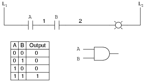
We can mimic the AND logic function by wiring the two contacts in series instead of parallel:

Boolean Equation
A=B.C 


Now, the lamp energizes only if contact A and contact B are simultaneously actuated. A path exists for current from wire L1 to the lamp (wire 2) if and only if both switch contacts are closed.

NOT Gate
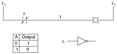
The logical inversion, or NOT, function can be performed on a contact input simply by using a normally-closed contact instead of a normally-open contact:
Boolean Equation 
Now, the lamp energizes if the contact is not actuated, and de-energizes when the contact is actuated.

NAND Gate
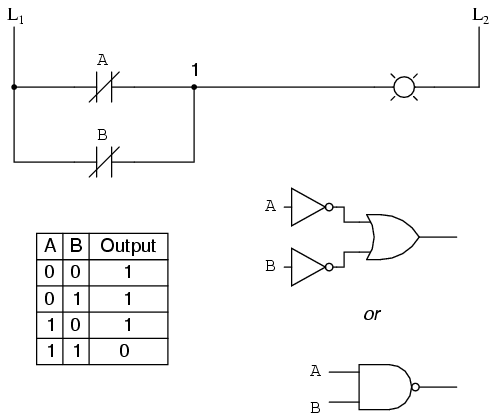
If we take our OR function and invert each "input" through the use of normally-closed contacts, we will end up with a NAND function. In a special branch of mathematics known as Boolean algebra, this effect of gate function identity changing with the inversion of input signals is described by DeMorgan's Theorem, a subject to be explored in more detail in a later chapter.

Boolean Equation 

The lamp will be energized if either contact is unactuated. It will go out only if both contacts are actuated simultaneously.

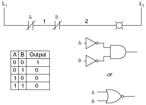
NOR Gate
Likewise, if we take our AND function and invert each "input" through the use of normally-closed contacts, we will end up with a NOR function:

Boolean Equation 

A pattern quickly reveals itself when ladder circuits are compared with their logic gate counterparts:


  • · Parallel contacts are equivalent to an OR gate. 
  • · Series contacts are equivalent to an AND gate. 
  • · Normally-closed contacts are equivalent to a NOT gate (inverter). 
XOR Gate
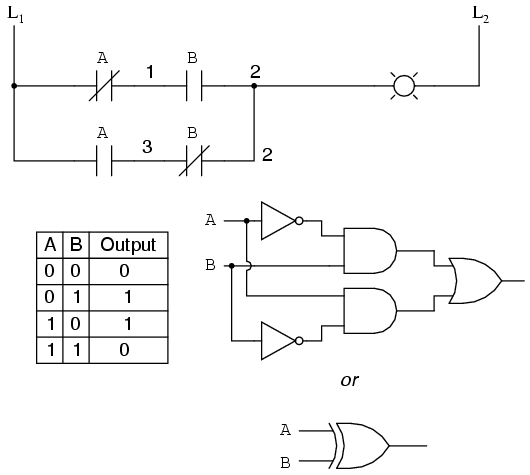
We can build combinational logic functions by grouping contacts in series-parallel arrangements, as well. In the following example, we have an Exclusive-OR function built from a combination of AND, OR, and inverter (NOT) gates:

Boolean Equation 

The top rung (NC contact A in series with NO contact B) is the equivalent of the top NOT/AND gate combination. The bottom rung (NO contact A in series with NC contact B) is the equivalent of the bottom NOT/AND gate combination. The parallel connection between the two rungs at wire number 2 forms the equivalent of the OR gate, in allowing either rung 1 or rung 2 to energize the lamp.

To make the Exclusive-OR function, we had to use two contacts per input: one for direct input and the other for "inverted" input. The two "A" contacts are physically actuated by the same mechanism, as are the two "B" contacts. The common association between contacts is denoted by the label of the contact. There is no limit to how many contacts per switch can be represented in a ladderdiagram, as each new contact on any switch or relay (either normally-open or normally-closed) used in the diagram is simply marked with the same label.

Sometimes, multiple contacts on a single switch (or relay) are designated by a compound labels, such as "A-1" and "A-2" instead of two "A" labels. This may be especially useful if you want to specifically designate which set of contacts on each switch or relay is being used for which part of a circuit. For simplicity's sake, I'll refrain from such elaborate labeling in this lesson. If you see a common label for multiple contacts, you know those contacts are all actuated by the same mechanism.

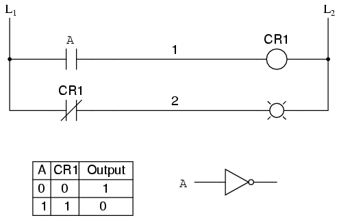
If we wish to invert the output of any switch-generated logic function, we must use a relay with a normally-closed contact. For instance, if we want to energize a load based on the inverse, or NOT, of a normally-open contact, we could do this:

We will call the relay, "control relay 1," or CR1. When the coil of CR1 (symbolized with the pair of parentheses on the first rung) is energized, the contact on the second rung opens, thus de-energizing the lamp. From switch A to the coil of CR1, the logic function is noninverted. The normally-closed contact actuated by relay coil CR1 provides a logical inverter function to drive the lamp opposite that of the switch's actuation status.

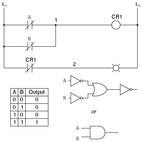
Applying this inversion strategy to one of our inverted-input functions created earlier, such as the OR-to-NAND, we can invert the output with a relay to create a noninverted function:


From the switches to the coil of CR1, the logical function is that of a NAND gate. CR1's normally-closed contact provides one final inversion to turn the NAND function into an AND function.

REVIEW:


  • · Parallel contacts are logically equivalent to an OR gate. 
  • · Series contacts are logically equivalent to an AND gate. 
  • · Normally closed (N.C.) contacts are logically equivalent to a NOT gate. 
  • · A relay must be used to invert the output of a logic gate function, while simple normally-closed switch contacts are sufficient to represent inverted gate inputs. 

Permissive and interlock circuits

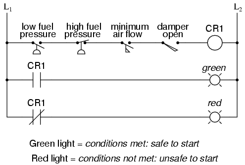
A practical application of switch and relay logic is in control systems where several process conditions have to be met before a piece of equipment is allowed to start. A good example of this is burner control for large combustion furnaces. In order for the burners in a large furnace to be started safely, the control system requests "permission" from several process switches, including high and low fuel pressure, air fan flow check, exhaust stack damper position, access door position, etc. Each process condition is called a permissive, and each permissive switch contact is wired in series, so that if any one of them detects an unsafe condition, the circuit will be opened:

If all permissive conditions are met, CR1 will energize and the green lamp will be lit. In real life, more than just a green lamp would be energized: usually a control relay or fuel valve solenoid would be placed in that rung of the circuit to be energized when all the permissive contacts were "good:" that is, all closed. If any one of the permissive conditions are not met, the series string of switch contacts will be broken, CR2 will de-energize, and the red lamp will light.

Note that the high fuel pressure contact is normally-closed. This is because we want the switch contact to open if the fuel pressure gets too high. Since the "normal" condition of any pressure switch is when zero (low) pressure is being applied to it, and we want this switch to open with excessive (high) pressure, we must choose a switch that is closed in its normal state.

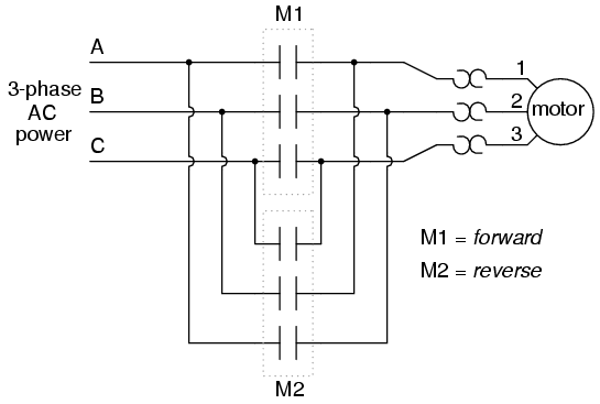
Another practical application of relay logic is in control systems where we want to ensure two incompatible events cannot occur at the same time. An example of this is in reversible motor control, where two motor contactors are wired to switch polarity (or phase sequence) to an electric motor, and we don't want the forward and reverse contactors energized simultaneously:


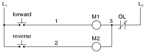
When contactor M1 is energized, the 3 phases (A, B, and C) are connected directly to terminals 1, 2, and 3 of the motor, respectively. However, when contactor M2 is energized, phases A and B are reversed, A going to motor terminal 2 and B going to motor terminal 1. This reversal of phase wires results in the motor spinning the opposite direction. Let's examine the control circuit for these two contactors:

Take note of the normally-closed "OL" contact, which is the thermal overload contact activated by the "heater" elements wired in series with each phase of the AC motor. If the heaters get too hot, the contact will change from its normal (closed) state to being open, which will prevent either contactor from energizing.

This control system will work fine, so long as no one pushes both buttons at the same time. If someone were to do that, phases A and B would be short-circuited together by virtue of the fact that contactor M1 sends phases A and B straight to the motor and contactor M2 reverses them; phase A would be shorted to phase B and vice versa. Obviously, this is a bad control system design!

To prevent this occurrence from happening, we can design the circuit so that the energization of one contactor prevents the energization of the other. This is called interlocking, and it is accomplished through the use of auxiliary contacts on each contactor, as such:

Now, when M1 is energized, the normally-closed auxiliary contact on the second rung will be open, thus preventing M2 from being energized, even if the "Reverse" pushbutton is actuated. Likewise, M1's energization is prevented when M2 is energized. Note, as well, how additional wire numbers (4 and 5) were added to reflect the wiring changes.

It should be noted that this is not the only way to interlock contactors to prevent a short-circuit condition. Some contactors come equipped with the option of a mechanical interlock: a lever joining the armatures of two contactors together so that they are physically prevented from simultaneous closure. For additional safety, electrical interlocks may still be used, and due to the simplicity of the circuit there is no good reason not to employ them in addition to mechanical interlocks.

REVIEW: 

  • Switch contacts installed in a rung of ladder logic designed to interrupt a circuit if certain physical conditions are not met are called permissive contacts, because the system requires permission from these inputs to activate. 
  • Switch contacts designed to prevent a control system from taking two incompatible actions at once (such as powering an electric motor forward and backward simultaneously) are called interlocks.

Data Acquisition System Components

A data acquisition system is designed to collect relevant measurement data for characterization, monitoring or control. The defined parameters of an application will determine the resolution, correctness, channel count and speed needs for a data acquisition system. There are a wide range of data acquisition systems and solutions available on the market. When implementing a data acquisition system, a detailed application requirement regarding capability and performance should be in place. The data acquisition system components are composed of devices, boards and equipment which gather data from external instruments and transforms the data into an analogue or digital (A/D) form for potential processing or signal conditioning.


Measurement Hardware


The most basic element of a data acquisition system is A/D Converter, which is used to convert DC voltages gained from the transducers into digital data. The gauged voltages may be equivalent to a certain temperature, pressure, flow or speed. Digital Input is another element of a data acquisition system which detects a digital bit pattern to examine whether an external device is on or off. Counter can be utilized to count incidents stemming from an external device. For instance, a counter card can be used to count the number of digital pulses.

Control Hardware
A D/A converter conducts the opposite functionality of an aforementioned A/D device. A D/A converter translates commands from the control hardware and transforms them into matching DC voltage or current. A Digital Output is another control hardware which receives commands from the control hardware and transforms them into a relevant digital bit pattern. The control switching card is used to provide power to external fans, pumps or valves through fulfilling an electrical circuit.

Switching


Electromechanical switches, including reed and armature relays, are important components in low-speed applications. A primary advantage is their capability to switch high-voltage and current levels; however, they are confined to switching rates of several hundred channels per second while electronic switches are utilized in high-speed applications. Multiplexer Configuration is mainly used for signal switching to a single measuring device. Normally, in the multiplexer configuration, only one signal is associated each time to the measuring device and the switching is break-before-make.
Signal Conditioning

This component is to magnify, attenuate, shape or segregate signals from transducers before they are transferred to the measurement hardware. Signal conditioning transforms the signal to a form which is better gauged by the system, or improves the chances of being measured. Transducers are instruments which convert physical parameters into electrical variables. The electrical variables are measured and the consequences are converted to engineering units.
Computer and Software

The computer can transfer data and store data for the data acquisition system while software enables communication between the computer and the hardware. Software can enable one to set the sampling rate of a board and obtain a predefined volume of data.

Data Acquisition System Tutorial

Data acquisition involves collecting signals from sources of measurement, storing them in digital format and presenting them on a PC. Choose from several technologies for data acquisition on personal computers, such as PCI, PCI Express, PXI, PXI Express, PCMCIA, USB, wireless and Ethernet. Automate the recording and measurement of data, and feed it to data analysis applications. Build a basic data acquisition system using transducers, sensors, signals, signal conditioning equipment, data acquisition hardware, device driver software and application software.

Instructions

1. Select a measuring instrument called a transducer to measure phenomena such as the room temperature, intensity of a light source or force applied to an object. For example, obtain a thermocouple or thermistor to measure temperature; or use a photo sensor to measure light intensity.

2. Find out the requirements of the transducer to convert the physical phenomenon into a measurable signal. Signals are classified as analog and digital signals. Analog signals take any value in a continuous range whereas digital signals take distinct values only. Voltage, temperature, pressure and sound are analog signals with the following characteristics: level or amplitude, shape (such as sine, cosine or sawtooth waves) and frequency. Each of these attributes can be measured on the transducer. Digital signals take two values, a low and a high. The low and high values are defined by a certain value of the phenomenon. Learn to measure the rate of a digital signal, or how many times the signal transitions between low and high within a unit of time, using your transducer screen.

3. Learn to select appropriate hardware for signal conditioning. Connecting the transducer to the data acquisition device may be too dangerous or not give accurate results. Use signal conditioning equipment, such as an amplifier, to smooth out the signal amplitude. You may also use a multiplexer to multiplex the signal with other signals. Multiplexing is a technique where two or more signals are sent over the same transferring line turn by turn.
4. Select data acquisition hardware. This is the equipment that interfaces between the computer and the incoming signals. Connect the transducer or signal conditioning hardware to the data acquisition hardware following the instructions in the user manual. Data acquisition devices provide analog and digital input or output, counters, timers or a combination of these functions. Familiarize yourself with the available data acquisition devices for the desktop computer platform.
5. Install the driver software for the data acquisition device using the instructions that came with the package. Device drivers are programs that communicate with the particular hardware device for which they are written; they provide an interface with the main computer.
6. Install the application software on your data acquisition platform computer. Buy a license for a vendor software package or have a team develop a custom-made program specifically tailored for the data. The application will store and process the digitized data.

Identification and Control Equipment


Identification and control equipment is used to collect and communicate the information that is used to coordinate the flow of materials within a facility and between a facility and its suppliers and customers. The major types of identification and communication equipment are:
  1. Manual (no equipment)
  2. Bar codes
  3. Radio frequency (RF) tag
  4. Magnetic stripe
  1. Machine vision
  2. Portable data terminal
  3. Electronic data interchange (EDI)/Internet
Top |

1. Manual (No Equipment)

The identification of materials and associated communication can be performed manually with no specialized equipment
Although it is sometimes possible to manually coordinate the operation of a material handling system, it becomes more difficult to due so as the speed, size, and complexity of the system increases
Top |

2. Bar Codes

Unique bar/space patterns represent various alphanumeric characters
Bar code system consists of bar code label, bar code scanner, and bar code printer
Contact bar code scanners use pen or wand to read labels
Noncontact bar code scanners include fixed beam, moving beam, and omnidirectional
1-D codes are most common; 2-D codes enable much greater data storage capability
Top |

3. Radio Frequency (RF) Tag

Data encoded on chip encased in a tag
Noncontact: can be read when the tag is within 30 ft. of an antenna
Tags can either be attached to a container, or permanently or temporarily to an item
RF tags have greater data storage capability than bar codes
Top |

4. Magnetic Stripe

Data encoded on a magnetic stripe that is readable in almost any environment
Requires contact with a reader
Greater storage capability and more expensive than bar codes
Top |

5. Machine Vision

Does not require explicit encoding of data since objects can be identified by their physical appearance
Noncontact, but typically requires structured lighting
More flexible than other identification equipment, but less robust
Top |

6. Portable Data Terminal

Handheld, arm-mounted, or vehicle-mounted data storage and communication device
Communicates with a host computer via a radio frequency or infrared link
Variety of input devices available: keyboard, bar code scanner, voice headset
Top |

7. Electronic Data Interchange (EDI)/Internet

Electronic data interchange (EDI) provides standards for inter-corporate transfer of purchase orders, invoices, shipping notices, and other frequently used business documents
Prior to the Internet, EDI required expensive dedicated value added networks (VANs)
EDI is critical for implementing JIT manufacturing
Top |

Storage Equipment


Storage equipment used for holding or buffering materials over a period of time. The major types of storage equipment are:
  1. Block stacking (no equipment)
  2. Selective pallet rack
  3. Drive-through rack
  4. Drive-in rack
  5. Flow-through rack
  6. Push-back rack
  7. Sliding rack
  8. Cantilever rack
  9. Stacking frame
  1. Shelves/bins/drawers
  2. Storage carousel
  3. Automatic storage/retrieval systems (AS/RS)
    1. Unit load AS/RS
    2. Miniload AS/RS
    3. Man-on-board AS/RS
    4. Deep-lane AS/RS
  4. Split case order picking system
  5. Mezzanine
The most common reason for storing a product allows the other elements of production to operate more efficiently on a per-unit basis because the fixed costs associated with utilizing the element can be spread over more products; e.g., storing up to a truckload of product in a facility reduces the per-unit costs of shipping; and buffering or storage of WIP enables batch production which reduces the per-unit setup costs.
Other potential reasons for storage include: time bridging—allows product to be available when it is needed (e.g., storing spare machine parts at the facility); processing—for some products (e.g., wine), storage can be considered as a processing operation because the product undergoes a required change during storage; and securing—e.g., nuclear waste storage.
Top |

1. Block Stacking (No Equipment)

Bulk storage using block stacking can result in the minimum cost of storage since cube utilization is high and no storage medium is required, but material accessibility is low since only the top of the front stack is accessible and loads at bottom of a stack must not require support
Storage racks are used when support and/or material accessibility is required
Top |

2. Selective Pallet Rack

Most popular type of storage rack
Pallets are supported between load-supporting beams
Special attachments and decking can be used to make the racks capable of supporting other types of unit loads besides pallets (e.g., coils, drums, skids)
Selective racks can be used for the following types of storage:
Standard—single-deep storage using a counterbalanced lift truck
Narrow-Aisle—storage using a narrow-aisle lift truck
Deep-Reach—greater than single-deep storage (typically double-deep storage)
Top |

3. Drive-Through Rack

Loads are supported by rails attached to the upright beams
Lift trucks are driven between the uprights beams
Requires similar-width loads
Open at both ends, allowing access from both ends (FIFO)
Top |

4. Drive-In Rack

Same as drive-through rack, except closed at one end, allowing entry from only one end (LIFO)
Top |

5. Flow-Through Rack

Loads are supported on an incline to enable gravity-based movement of the loads within the rack (via, e.g., a gravity roller conveyor)
Loaded at the higher end and unloaded at the lower end (FIFO)
Top |

6. Push-Back Rack

Same as push-back rack, except loaded and unloaded at the lower end and closed at the higher end (LIFO)
Top |

7. Sliding Rack

Only one mobile aisle is used to access several rows of racks
Location of the aisle is changed by sliding the rows of racks along guide rails in the floor
Typically found in library stacks
Top |

8. Cantilever Rack

Loads are supported by cantilever "arms"
Used to store long loads (e.g., bar stock, pipes, lumber)
Similar to pallet racks, except the front upright beams and the front supporting beams are eliminated
Top |

9. Stacking Frame

Interlocking units that enable stacking of a load so that crushing does not occur
Can be disassembled and stored compactly when not in used
Pallet frames can be used to enable multilevel block stacking
Top |

10. Shelves/Bins/Drawers

Top |

11. Storage Carousel

Carousel consists of a set of vertically or horizontally revolving storage baskets or bins
Materials (and the storage medium) move to the operator, "part-to-man," for end-of-aisle picking
Each level of the carousel can rotate independently in a clockwise or counter-clockwise direction
Control ranges from manually activated push buttons to automated computer controlled systems
Provides an alternative to typical "man-to-part" AS/RS, where the S/R machine moves to the part
Similar to a trolley conveyor with storage baskets
Top |

12. Automatic Storage/Retrieval Systems (AS/RS)

Consists of an integrated computer-controlled system that combines the storage medium, transport mechanism, and controls with various levels of automation for fast and accurate random storage of products and materials
Storage/retrieval (S/R) machine in an AS/RS operates in narrow aisle, serving rack slots on both sides of aisle; can travel in horizontal (along the aisle) and vertical (up and down a rack) directions at same time
Advantages: fewer material handlers, better material control (including security), and more efficient use of storage space
Disadvantages: high capital and maintenance costs, and difficult to modify

12(a) Unit Load AS/RS

Used to store/retrieve loads that are palletized or unitized and weigh over 500 lbs.
Stacking heights up to 130 ft. high, with most ranging from 60 to 85 ft. high; 5 to 6 ft. wide aisles; single- or double-deep storage racks

12(b) Miniload AS/RS

Used to store/retrieve small parts and tools that can be stored in a storage bin or drawer
End-of-aisle order picking and replenishment
Stacking heights range from 12 to 20 ft.; bin capacities range from 200 to 750 lbs.
Termed a "microload AS/RS" when used in assembly, kitting, and testing operations to deliver small containers of parts to individual workstations, where workstations are typically located on the sides of a pair of racks and the S/R machine operates between the racks to move containers to openings in the racks (storage lanes) located next to each station

12(c) Man-On-Board AS/RS

Used for in-aisle picking; operator picks from shelves, bins, or drawers within the storage structure
Manual or automatic control
S/R machine is similar to an order picker or turret truck and can sometimes operate as an industrial truck when outside an aisle, except the S/R is guided along a rail when operating in an aisle

12(d) Deep-Lane AS/RS

Similar to unit load AS/RS, except loads can be stored to greater depths in the storage rack
A rack-entry vehicle is used to carry loads into the racks from the S/R machine, and is controlled by the S/R machine
Termed an "automated item retrieval system" when used to automatically retrieve individual items or cases, with replenishment (storage) taking place manually from the rear of a flow-through storage lane and items are pushed forward with a rear-mounted pusher bar for automatic picking from the front of the storage lane
Top |

13. Split-Case Order Picking System

Unlike an AS/RS, a split-case order picking system enables fully automated picking of individual items
Two general categories of split-case order picking system are robotic based systems and magazine/dispenser based systems
Robotic based systems are similar in construction to robotic pick and place palletizers
Magazine/dispenser based systems are similar to vending machines, but larger in scale
"A-Frame" dispenser system (pictured) is popular within pharmaceutical distribution centers; items are dispensed onto a belt conveyor that carries them into a container
Top |

14. Mezzanine

Inexpensive means of providing additional storage or office space
Makes use of clear space over activities not requiring much headroom (e.g., restrooms, block storage, etc.)
At least 14 ft. of clear space is needed for a mezzanine
Top |