
Introduction
Labview from National Instruments (NI) is build upon a purely graphical, general-purpose programming language, G, with extensive libraries of functions, an integral compiler and debugging, and an application builder for stand-alone applications. The concept of VIs (Virtual Instruments), invented by National Instruments, permits the building of powerful instrumentation and control to run anywhere and everywhere.
Objectives
Making use of Labview and DAQ (Data Acquisition) device, build a VI (Virtual Intrument) with a switch that lights up a LED. The project is next extended to control the VI from Internet.
Pre-Requirements
Installed Labview and DAQmx softwares, and a DAQ device duly working and recognised by Labview.
Required Equipment
NI Labview 8.6 Student or higher
NI DAQmx 8.6 or higher
NI USB-6009 DAQ device
200 ohms 1/4W resistor
5mm red LED
NI DAQmx 8.6 or higher
NI USB-6009 DAQ device
200 ohms 1/4W resistor
5mm red LED
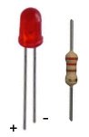
The Electronic Circuit

A Simple VI
STEP 1 - Start Labview
STEP 2 – A new window is opened Getting Started

STEP 3 – Under Files menu, start a new VI pressing on Blank VI link. It will open the Front Panel of a new untitled blank VI.

STEP 4 - On the Front Panel workspace, right click with mouse and choose Controls,Buttons & Switches -> Push Button

Now place the Push Button on the Front Panel workspace

STEP 5 – On Window menu of Front Panel choose Show Block Diagram

Block Diagram window will be opened. It will already contain the Push Button function

STEP 6 – Right click with mouse the Block Diagram workspace and choose Functions – > Input -> DAQ Assistant

Place adequately the DAQ Assistant function on the Block Diagram workspace. DAQ Assistant will be immediately initialized

STEP 7 - Create New Express Task window will be opened. Choose Generate Signals

STEP 8 – A sub-menu will be opened. Choose Digital Output
 STEP 9 - Another sub-menu will be opened. Choose Line Output.
STEP 10 - A new window will opened. Under Supported Physical Channels chooseport0line0

Press Finish
STEP 11 - A new window of DAQ Assistant will be opened

Leave all default values as they are, and press OK.
STEP 12 - Block Diagram will be opened, and VI will be build.
 STEP 13 - Block Diagram will have now configured DAQ device.
 STEP 14 - Connect Boolean function with data input of DAQ Assistant
The link will be broken with an error message:
“You have connected a scalar type to an array of that type. The type of the source is Boolean (TRUE or FALSE). The type of the sink is 1-D array of Boolean (True or False)”
Hence we need to place the Boolean function in an Array.
STEP 15 - Press the right button of the mouse on the link, and delete the link
 The Wire Branch will be removed
Before doing anything else, it is safe to save the VI. Under File menu of the Block Diagram, choose Save as and save the VI as switchled_usb6009.vi
STEP 16 - Press the right button of mouse and choose extra set of Controls clicking the button on the arrow pointing downwards, just below RF Communications controls
 Choose Modern -> Array, Matrix & Cluster -> Array
 STEP 17 - Place it on the Front Panel workspace
After selecting the Push Button Boolean, drag it and drop into Array box. The Push Button will become part of the Array
 STEP 18 - Now select the Block Diagram
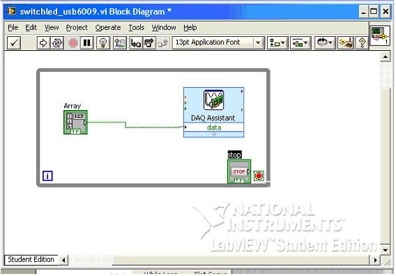
 Connect the new Array function (containing the Boolean Push Button) to data input ofDAQ Assistant function. This time the link will show no error.
STEP 19 - It is a good practise to place the functions within a While Loop with a STOP button. Right click with mouse button on the Block Diagram, and choose Execution Control – > While Loop

Place the While Loop around Array and DAQ Assistant functions, starting from just on top left of Array function, and ending below DAQ Assistant function allowing automatic placing of stop button that comes with While Loop.


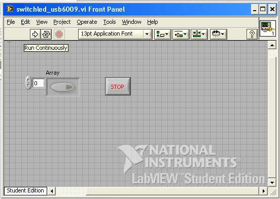
STEP 21 - Hopefully it is all OK now and we can save the VI, in Front Panel with File -> Save
STEP 22 – Press the virtual button run continuously 

and then press the virtual button and the arrow with light up

And so will light up the LED in the real circuit

Conclusions
With just a couple of electronic components and NI tools, we have build step by step a Virtual Instruments (VI). It is is is quite easy with the graphic programming language of Labview.
No comments:
Post a Comment